|
Rather than
re-cycling the same main picture of the painted aircraft, I decided to include a
picture of our other "child". Skipper is an 8 year old
Schipperke that my wife had before I met her. Skipper and Tiger get along
very well, and really enjoy playing with each other.
Skipper pretty much
avoids my workshop, but will come to visit once in a while 
For the camera buffs
who wonder what camera I used for the pictures, I'm currently using a Pentax
EI-200, but a Pentax *ist-DS is in the near future :-) I've been using
Pentax equipment since high school, and they finally came out with a digital SLR
that uses K-mount lenses that is parity priced with similar offerings from Canon
and Nikon!
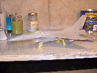
On to the airplane
stuff!!!! Steps 46-53 are the final airframe assembly prior to painting
| Steps 46/47 -
Wingtip navigation lights and Mounting the engine
Step 46 is straight
forward. I masked off the nav lights top and bottom with Ambroid
Liquid mask and secured the rods with CA adhesive and the nav lights with
Ambroid solvent glue
Mounting the engine is
straight forward. Since on this kit, the engine won't be removable,
once I had the engine securely seated, I ran a bead of Ambroid in the
seam, and clamped it up with some mini-clams from the wheel well the
engine nozzle. There was just one small area that needed a bit of
filler, but it wasn't much. |
Click on
image below to see larger image
|
|
|
Step 48/49 - Vertical Fin
Assembly and mounting
No surprises here either.
Be sure to remember to drill the holes for the small vents on either side of the
vertical stabilizer. I forgot, and had to hold the fin up to a very bright
light to see where to drill.
The 3 poly caps are for the
rudder to pivot in, and for mounting to the fuselage.
You could leave the antenna (Part
C19) off until the vertical stabilizer is mounted.
I would also leave part L6 off
until later (after painting and decaling).
I left the rudder and fin cap off
until after the vertical stabilizer is mounted since I was gluing it on.
| If you are
building the kit with the engine non-removable, then in step 49 do not
glue the vertical stabilizer to the fuselage.
I left the lights off (will
be put on the same time as the flare/chaff dispensers).
After mounting the vertical
stabilizer and it was dry (no filler required). I added the rudder and fin
cap.
I masked the lens on the
fin cap with liquid mask as well. |
Click on
image below to see larger image
|
|
|
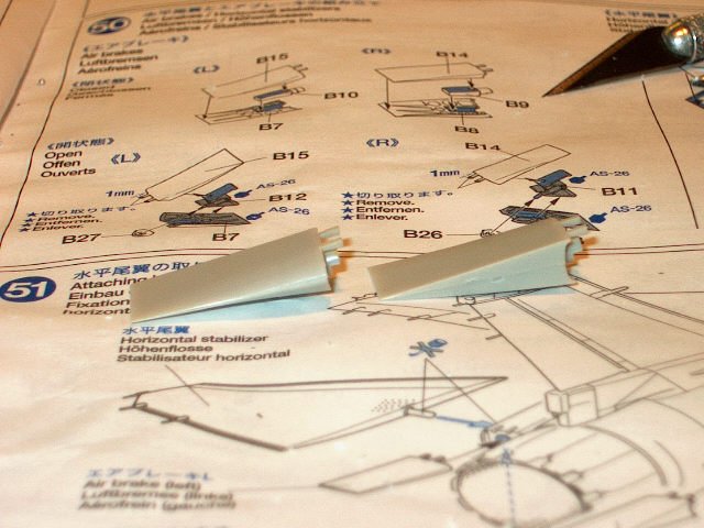
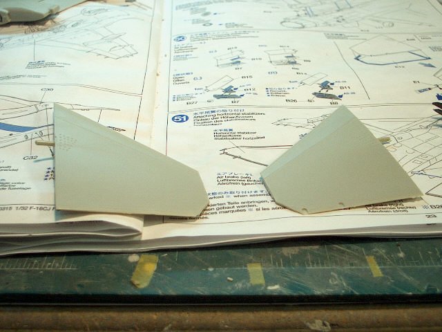
| Step 50/51 --
Speed brakes and horizontal stabilizers
It's up to the builder on
whether or not to build the speed brakes open or closed. From
reading the Squadron Walk Around book, there is no hard and fast rule on
whether or not they are open when the airplane isn't powered up. For
this particular, I built them closed.
The horizontal stabilizers
are symmetric (there is no left/right stabilizer). One will have the
static wick holders on top, and one will have them on the bottom.
Care is needed to properly
clamp the upper and lower surfaces together so there is no step where they
meet.
I would leave the wick
holders off until after sanding the edges, especially to avoid knocking
off part E1
Mounting the speed brakes
and horizontal stabilizers is simplicity. They only fit one way.
|
|
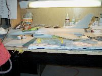
Step 52 -- masking and painting
canopy
Quite a few notes here.
From looking at the Squadron
book, I realized that there was a black seam on the canopy that wasn't going to
be painted the fuselage color, and I forgot to take pictures, but in the
finished kit, there will be close up photos once the canopy is decaled and dull
coated.
I started by masking off the
canopy with Ambroid liquid mask, masked off the inside with drafting tape (it's
less tacky than regular masking tape, and wider than my normal Tamiya tape), and
sprayed the canopy flat black (both front and rear sections).
From the photos I've seen, the
rear canopy framework is black (not the color of the fuselage).
Once the paint was dry on the
forward canopy, I masked off what is supposed to be remain flat black. The
areas that this is a small "strip" along the bottom between the canopy
and the framework, on the rear canopy bow, between the canopy and the framework.
Tamiya molded the demarcation
between the areas on the bottom, but not on the bow. From studying the
photos in the Squadron book, it appears that the demarcation is just forward of
the rivet line that goes around the canopy bow.
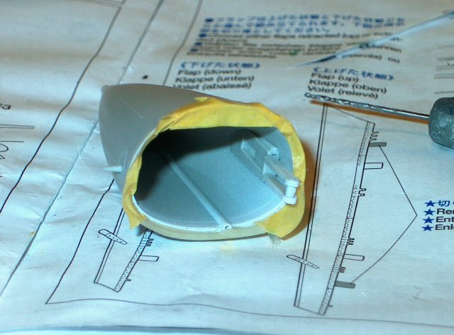
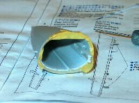
Step 53 -- Radome assembly,
attaching radome and paint prep
Radome assembly is simple, but
painting isn't
The easiest thing I found is to
Attach part F33, but not F34
Paint the lip and Part F44 flat
white.
| Mask off, and
then spray the interior of the radome. The color call out is Tamiya
XF-71 Cockpit green. I took this to be green zinc chromate.
Once it was dry, I attached Part 34, let it dry and then mounted the
radome and
I then clipped the
radome onto the fuselage, and glued in place with Ambroid. I had a couple
of small spots on the seam to fill with my thinned mixture of Squadron
White Putty and lacquer thinner, but they were tiny spots.
I also left off the pitot
tube off the radome, as I was worried about stabbing myself with it
(actually, knocking it off down road)
Steve |
Click on
image below to see larger image
|
|
|
|
|
|